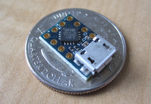
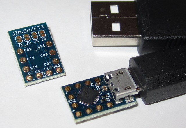
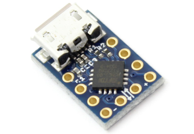
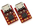
The MicroFTX is a low-cost, reconfigurable, and compact Micro-USB breakout board based on the FTDI FT230X full-speed USB Serial UART IC.

News
October 2017
- The MicroFTX is out of stock. Please consider the Micro1v8 for an improved version of the MicroFTX with LEDs and out-of-the-box support for 1.8V serial devices.
Where to Buy
The MicroFTX is out of stock. Please consider the Micro1v8 for an improved version of the MicroFTX with LEDs and out-of-the-box support for 1.8V serial devices.

|
Micro1v8 (2-Pack) - USB to 1.8V Serial Adapter with LEDs - FTDI FT230X chip |
International buyers: Our inventory is "Fulfilled by Amazon" which means that it's up to Amazon to decide where they ship. Currently, they do offer international shipping on our products to most countries. Thank you!
Uses
- USB to serial interface for microcontroller development or debugging
- Reverse-engineering tool with flexible I/O voltages (1.8V, 2.5V, 3.3V, etc)
- Battery charger detection for high-power USB applications (app note)
- Bitbang GPIO mode for simple digital input and output
Features
- FT230XQ (website, datasheet) from FTDI’s new X-Chip series
- Revision D silicon (date code 1246-D) or later
- Tiny footprint – only 0.4" x 0.64" including Micro-USB B connector
- Standard 0.1" headers expose all signals
- Easy solder-jumper configuration
- Supports I/O voltages from 1.8V to 3.3V, with 5V tolerance
- UART baudrates up to 3 Mbaud
- Solid FTDI driver support for Windows, OS X, and Linux
- Programming interface is similar to the FT232R series chips
- Internal reprogrammable EEPROM for VID/PID and other customization
- Professionally manufactured, with gold plating for easy solderability
- Unique pre-programmed serial number
- Open design
Pinout
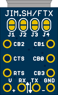
10 signals are brought out to pin holes with 0.1" spacing. They fit standard 0.1" male or female headers, or it’s also easy to just solder wires directly.
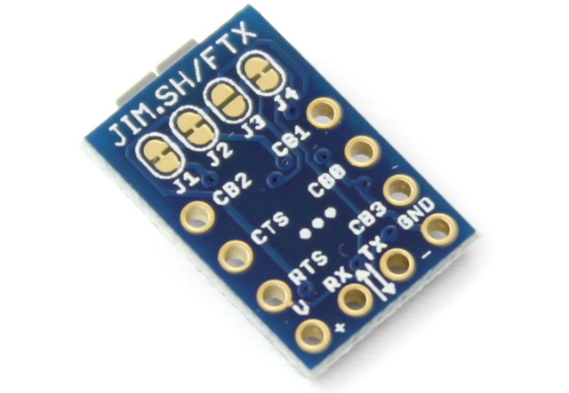
For many uses, the four pins along the lower edge (V, RX, TX, GND) are all you’ll need. The signal names are shown on the bottom of the PCB.
Most of these pins are configurable! The CBx pins have a bunch of options that can be changed by reprogramming the EEPROM. Even without changing the EEPROM, it’s easy to reuse the CTS, RTS, RX, and TX pins as simple digital I/O.
Looking at the bottom of the PCB, counterclockwise from the top left:
| Pin | FTDI Name | Description |
|---|---|---|
CB2 |
CBUS2 | Configurable I/O pin (default: TXLED) |
CTS |
CTS# | Clear To Send handshake signal (CTS) |
RTS |
RTS# | Request To Send handshake signal (RTS) |
V |
– | Voltage pin (see jumper configuration options below) |
RX |
RXD | Receive data (in UART mode, an input to the MicroFTX) |
TX |
TXD | Transmit data (in UART mode, an output from the MicroFTX) |
GND |
GND | Ground |
CB3 |
CBUS3 | Configurable I/O pin (default: SLEEP) |
CB0 |
CBUS0 | Configurable I/O pin (default: TXDEN) |
CB1 |
CBUS1 | Configurable I/O pin (default: RXLED) |
For a simple but useful addition, add LEDs betwen V (anode) and CBUS1/CBUS2 (cathode) to get activity indicators on transmit and receive.
Jumper Configuration
The MicroFTX has four solder jumpers on the bottom side, labeled J1 through J4, that configure how voltages are connected between the FTDI chip, the V pin, and the USB port.
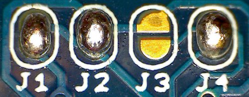
From the factory, MicroFTX boards ship in configuration #1 as shown above.
For Revision 3 boards, shipped starting June 2016, this default configuration is set with small traces between the pads, as indicated by arrows below:
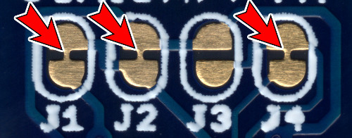
To select an alternate configuration, first use a sharp knife to cut the three marked traces. **Be careful not to cut into other traces between the jumpers**. A multimeter can be used to test continuity and verify that the traces were fully cut before proceeding.
To close  a solder jumper, add solder to both pads until a bridge is formed between them.
To open  a previously-closed solder jumper, use a clean soldering iron or wick to remove the excess solder until the bridge goes away.
Valid configurations
| J1 | J2 | J3 | J4 | Power Source | `V` pin | I/O voltage | Notes | |
|---|---|---|---|---|---|---|---|---|
| #1 | |
|
|
|
USB | 5V out | 3.3V | a, b |
| #2 | |
|
|
|
USB | 3.3V out | 3.3V | a, c |
| #3 | |
|
|
|
USB | 1.8V - 3.3V in | 1.8V - 3.3V | d |
| #4 | |
|
|
|
V pin | 5V in | 3.3V | a |
| #5 | |
|
|
|
V pin | 3.3V in | 3.3V | a |
| #6 | |
|
|
|
USB | no connection | 3.3V | a |
|
Notes: a. I/O voltage is 5V tolerant b. 5V output current is limited by what the USB port can supply c. 3.3V output current is 50mA max d. I/O voltage is set by the voltage applied to the V pin |
||||||||
Other jumper configurations will result in the board not powering up, or could potentially damage the chip.
Drivers
Windows, Mac OS X
FTDI provides two types of drivers for their chips, including the FT230X that powers the MicroFTX:
- VCP (“Virtual COM Port”) makes the device appear as a serial port
- D2XX provides an API for bitbang and other direct access
To support the FT-X series chips, you need driver version 2.08.23 or later (Windows) or 2.2.17 or later (OS X).
Note that the FT-X EEPROM contains a bit which determines whether the Windows driver will create a Virtual COM Port (VCP) for a particular device. By default it does create one, but you can use FTDI’s FT_Prog utility to check or change the default. You can also force it to create a COM port by going into the device manager and overriding the settings manually.
Linux (serial port)
FTDI chips are handled by the kernel driver ftdi_sio and create a serial device named like /dev/ttyUSB0. All Linux distributions should support it out-of-the-box these days.
To allow non-root access to the /dev/ttyUSB* device nodes, add your user to the dialout group and log-in again:
$ adduser $USER dialoutLinux (direct access)
If you don’t need the device node, or if you want to use bitbang IO like in the example below, a library like libftdi can be used independently of the kernel version.
To allow non-root access with libftdi or similar, create (or download) a file named /etc/udev/rules.d/10-ftx.rules containing:
SUBSYSTEM=="usb", ACTION=="add", \
  ATTRS{idVendor}=="0403", ATTRS{idProduct}=="6015", GROUP="plugdev"
Comparison to Older Chips
The FT230X is very similar to FTDI’s older chips, like the FT232R series. In general, a lot of code and tools for the FT232R are likely to work with few changes.
Feature comparison
FT230X has larger 512/512 byte receive/transmit buffers. This improves on the FT232R’s 256/128 byte receive/transmit buffers, and should improve reliability and throughput at higher baud rates.
FT230X has battery charger detection, to allow circuits to know when it’s safe to draw high currents from USB chargers.
FT230X is smaller, lower cost, and has lower power consumption.
FT232R had more pins that included the full set of RS232 control signals, such as DCD, DTR, RI, etc. The FT230X is smaller, and so it has a more limited pinout.
FT232R could drive 5V on its outputs. The FT230X can only output 3.3V levels, although the inputs are still 5V tolerant, and it should therefore be able to interface with most 5V systems without trouble.
Migrating code and drivers
From a software point of view, the FT232R and FT230X interfaces are very similar. Baudrate generation, bitbang mode, and other USB low-level commands are the same. The only driver changes in Linux to support the FT230X, for example, were to include the new product ID and to otherwise treat the chip as a FT232R.
| USB Parameter | FT232R | FT230X |
|---|---|---|
| idVendor | 0x0403 | 0x0403 |
| idProduct | 0x6001 | 0x6015 |
| bcdDevice | 0x0400 | 0x1000 |
Bitbang GPIO
The FT230X supports bitbang GPIO (general-purpose input/output) modes that allow you to set and read digital pins directly. It’s a great way to let your computer drive a simple binary output, or to read the state of a switch. For full details, see the FT230X website and datasheet. FTDI’s bitbang app note AN232R-01 hasn’t been updated for the FT-X series of chips yet, but the setup and usage of bitbang mode is essentially the same.
Two forms of bitbang are supported. They are enabled with FD_SetBitMode (D2XX) or ftdi_set_bitmode (libftdi):
BITMODE_BITBANGuses theRX,TX,CTS, andRTSpins and works out of the boxBITMODE_CBUSuses theCBxpins, but needs to be enabled first in the EEPROM
On Linux, libftdi provides a pretty easy way to use bitbang. The python bindings are poor, but it’s straightforward in C. This program will toggle the RX, TX, CTS, and RTS pins every time it’s run:
#include <ftdi.h>
#include <err.h>

int main(int argc, char *argv[])
{
    struct ftdi_context ftdi;
    unsigned char x;

    /* Initialize and find device */
    if (ftdi_init(&ftdi) < 0)
        err(1, "ftdi_init");

    if (ftdi_usb_open(&ftdi, 0x0403, 0x6015) < 0)
        err(2, "can't open device");

    /* Enable bitbang */
    if (ftdi_set_bitmode(&ftdi, 0xff, BITMODE_BITBANG) < 0)
        err(3, "can't enable bitbang mode");

    /* Read state & flip it */
    if (ftdi_read_pins(&ftdi, &x) < 0)
        err(4, "can't read");
    x ^= 0xff;
    if (ftdi_write_data(&ftdi, &x, 1) < 0)
        err(5, "can't write");

    /* Close device */
    ftdi_usb_close(&ftdi);
    ftdi_deinit(&ftdi);

    return 0;
}
To test it out, download this file as ftdi-bitbang.c, compile, and run it:
$ sudo apt-get install libftdi-dev build-essential
$ gcc -o ftdi-bitbang ftdi-bitbang.c -lftdi
$ ./ftdi-bitbang
Non-standard Baudrates
The FT230X supports custom baudrates up to 3Mbaud. If you’re using Python’s pySerial module, custom baudrates should just work like any other baudrate:
#!/usr/bin/python
import serial

ser = serial.Serial(port = "/dev/ttyUSB0", baudrate = 2000000)
ser.write("hello, world")
ser.close()
Here is a low-level example of how to configure custom baudrates in C on a Linux system:
#include <termio.h>
#include <fcntl.h>
#include <err.h>
#include <linux/serial.h>

static int rate_to_constant(int baudrate) {
#define B(x) case x: return B##x
    switch(baudrate) {
        B(50);     B(75);     B(110);    B(134);    B(150);
        B(200);    B(300);    B(600);    B(1200);   B(1800);
        B(2400);   B(4800);   B(9600);   B(19200);  B(38400);
        B(57600);  B(115200); B(230400); B(460800); B(500000);
        B(576000); B(921600); B(1000000);B(1152000);B(1500000);
    default: return 0;
    }
#undef B
}

/* Open serial port in raw mode, with custom baudrate if necessary */
int serial_open(const char *device, int rate)
{
    struct termios options;
    struct serial_struct serinfo;
    int fd;
    int speed = 0;

    /* Open and configure serial port */
    if ((fd = open(device,O_RDWR|O_NOCTTY)) == -1)
        return -1;

    speed = rate_to_constant(rate);

    if (speed == 0) {
        /* Custom divisor */
        serinfo.reserved_char[0] = 0;
        if (ioctl(fd, TIOCGSERIAL, &serinfo) < 0)
            return -1;
        serinfo.flags &= ~ASYNC_SPD_MASK;
        serinfo.flags |= ASYNC_SPD_CUST;
        serinfo.custom_divisor = (serinfo.baud_base + (rate / 2)) / rate;
        if (serinfo.custom_divisor < 1)
            serinfo.custom_divisor = 1;
        if (ioctl(fd, TIOCSSERIAL, &serinfo) < 0)
            return -1;
        if (ioctl(fd, TIOCGSERIAL, &serinfo) < 0)
            return -1;
        if (serinfo.custom_divisor * rate != serinfo.baud_base) {
            warnx("actual baudrate is %d / %d = %f",
                  serinfo.baud_base, serinfo.custom_divisor,
                  (float)serinfo.baud_base / serinfo.custom_divisor);
        }
    }

    fcntl(fd, F_SETFL, 0);
    tcgetattr(fd, &options);
    cfsetispeed(&options, speed ?: B38400);
    cfsetospeed(&options, speed ?: B38400);
    cfmakeraw(&options);
    options.c_cflag |= (CLOCAL | CREAD);
    options.c_cflag &= ~CRTSCTS;
    if (tcsetattr(fd, TCSANOW, &options) != 0)
        return -1;

    return fd;
}
Download this example: linux-custom-baudrate.c.
EEPROM Customization
The FT230X includes a 2048-byte reprogrammable EEPROM that configures the chip. Features that can be customized in the EEPROM include:
- USB vendor ID, product ID, device strings
- Device serial number
- I/O pin drive strength
- UART signal polarity inversion
- CBUS pin configuration, allowing each pin to be selected as:
- TX/RX LED outputs
- Clock output (6 MHz, 12 MHz, 24 MHz)
- USB frame toggle (toggles every USB frame)
- USB sleep status and control
- Battery charge detection output
- Bitbang GPIO
- etc.
The easiest way to reprogram the EEPROM is using FTDI’s FT_Prog utility for Windows. Version 2.6.6 and later support the FT-X series chips. The user manual has more information.
The open-source libftdi library includes functions to access and change the EEPROM contents, and a standalone utility ftdi_eeprom that uses these functions. However, libftdi’s FT-X support is not necessarily complete and may not yet have been updated to support the FT-X chips. Note that incorrectly changing the EEPROM contents may lead to a chip that is difficult to recover.
Other third-party tools to program the EEPROM exist, like ftx-prog.
Design Files
Use these for reference, or if you want to incorporate this design into your own boards. Note that Eagle is required to open the layout files.
Revision 1 was sold before June 2013; may include FTDI chips with known errata.
- ftx-r1-schematic.pdf (PDF schematic)
- ftx-r1-layout.pdf (PDF layout)
- ftx-r1.zip (Eagle PCB schematic and layout)
Revision 2 can be identified by 2 white dots on the bottom silkscreen, and incorporates new FTDI chip revisions and larger capacitors.
- ftx-r2-schematic.pdf (PDF schematic)
- ftx-r2-layout-top.pdf (PDF layout, top)
- ftx-r2-layout-bot.pdf (PDF layout, bottom)
- ftx-r2.zip (Eagle PCB schematic and layout)
Revision 3 can be identified by 3 white dots on the bottom silkscreen. The default configuration is now set by traces which must be cut to change.
- ftx-r3-schematic.pdf (PDF schematic)
- ftx-r3-layout-top.pdf (PDF layout, top)
- ftx-r3-layout-bot.pdf (PDF layout, bottom)
- ftx-r3.zip (Eagle PCB schematic and layout)

MicroFTX by Jim Paris is
licensed under a Creative Commons
Attribution-ShareAlike 3.0 Unported License
Works incorporating (or based on) this design must attribute "MicroFTX by Jim Paris" and link to this page.
FTDI Errata
FTDI has announced some errors in very early (Revision B) versions of the FT230XQ chip, which were used in MicroFTX boards sold in 2012. These errors, and their workarounds, are detailed in FTDI’s Technical Note TN_139.
All MicroFTX boards shipped since June 2013 have Revision D or later silicon, which resolves all known issues.
Contact
For questions or comments, e-mail hwsupport@jim.sh.